
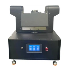
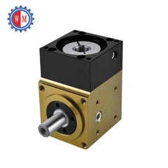
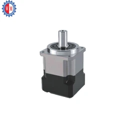
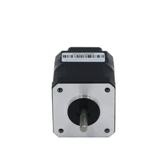


As a leading supplier of Integrated Servo Motors, I often receive inquiries from customers regarding the wiring process of these advanced motors. Wiring an Integrated Servo Motor correctly is crucial for its optimal performance and longevity. In this blog post, I will guide you through the step - by - step process of wiring an Integrated Servo Motor, ensuring that you can achieve a seamless installation.
Understanding the Basics of an Integrated Servo Motor
Before we dive into the wiring process, it's essential to understand what an Integrated Servo Motor is. An Integrated Servo Motor combines the motor, drive, and often some form of feedback device into a single unit. This integration simplifies the installation process and reduces the amount of space required in a control system. It is widely used in various applications such as robotics, CNC machines, and automated manufacturing systems.
Tools and Materials You Will Need
To wire an Integrated Servo Motor, you will need the following tools and materials:
- Wire strippers: To strip the insulation from the wires.
- Crimping tool: If you are using crimp connectors.
- Screwdriver: For tightening terminal screws.
- Electrical tape: To insulate the connections.
- Appropriate wires: The gauge of the wires depends on the current requirements of the motor. Refer to the motor's datasheet for the correct wire gauge.
- Power supply: A suitable power supply that meets the voltage and current requirements of the Integrated Servo Motor.
Step 1: Safety First
Before you start wiring, ensure that the power supply is turned off. Working on live electrical circuits can be extremely dangerous and may result in electric shock or damage to the equipment. Also, wear appropriate safety gear such as insulated gloves.
Step 2: Identify the Motor Terminals
Every Integrated Servo Motor has specific terminals for power, control, and feedback. Refer to the motor's wiring diagram, which is usually provided in the user manual or datasheet. The main terminals you need to identify are:
- Power terminals: These are used to connect the motor to the power supply. The power terminals typically include positive (+) and negative (-) connections for DC power or three - phase connections for AC power.
- Control terminals: These are used to send control signals to the motor, such as speed and position commands.
- Feedback terminals: These are used to connect the feedback device (e.g., encoder) to the motor, allowing it to monitor its position and speed accurately.
Step 3: Connect the Power Supply
Once you have identified the power terminals, connect the appropriate wires from the power supply to the motor. If you are using a DC power supply, connect the positive wire to the positive terminal of the motor and the negative wire to the negative terminal. For AC power, make sure to connect the three - phase wires correctly according to the wiring diagram.
It is important to note that the power supply voltage and current should match the motor's requirements. Using an incorrect power supply can damage the motor or cause it to malfunction.
Step 4: Connect the Control Signals
The control signals are used to regulate the motor's operation. The most common control signals are analog or digital signals for speed and position control. Connect the control wires from your control system (e.g., a PLC or a motion controller) to the corresponding control terminals on the motor.
Make sure to follow the wiring diagram carefully to ensure that the control signals are sent and received correctly. Some motors may require additional signal conditioning or isolation to prevent interference.
Step 5: Connect the Feedback Device
The feedback device is an essential part of an Integrated Servo Motor as it allows the motor to maintain accurate position and speed control. Connect the wires from the feedback device (such as an encoder) to the feedback terminals on the motor.
The feedback device provides information about the motor's position and speed, which is used by the motor's control system to make adjustments. Ensure that the feedback device is properly calibrated and configured according to the motor's requirements.
Step 6: Insulate the Connections
After making all the connections, use electrical tape to insulate the exposed wires and terminals. This helps to prevent short circuits and electrical interference. Make sure that the insulation is secure and covers all the connections completely.
Step 7: Test the Motor
Once you have completed the wiring, turn on the power supply and test the motor. Start with a low - speed test to ensure that the motor is running smoothly and that the control signals are working correctly. Monitor the motor's performance and check for any abnormal noises or vibrations.


If you encounter any problems during the test, turn off the power supply immediately and check the wiring connections. Refer to the motor's troubleshooting guide or contact our technical support team for assistance.
Troubleshooting Common Wiring Issues
- No power: Check the power supply connections to ensure that they are secure and that the power supply is providing the correct voltage and current.
- Motor not responding to control signals: Check the control wire connections and make sure that the control signals are being sent correctly. You may also need to check the configuration of the control system.
- Inaccurate position or speed control: Check the feedback device connections and make sure that the feedback device is properly calibrated.
Importance of Using High - Quality Components
When wiring an Integrated Servo Motor, it is crucial to use high - quality wires, connectors, and power supplies. Low - quality components can cause electrical interference, voltage drops, and other issues that can affect the motor's performance.
As a supplier, we offer a wide range of high - quality Integrated Servo Motor and Drive Kit that are designed to work together seamlessly. Our kits include everything you need for a successful installation, from the motor and drive to the necessary wiring and connectors.
Conclusion
Wiring an Integrated Servo Motor may seem daunting at first, but by following the steps outlined in this blog post, you can ensure a successful installation. Remember to prioritize safety, follow the wiring diagram carefully, and use high - quality components.
If you have any questions or need further assistance with wiring your Integrated Servo Motor, our team of experts is here to help. We are committed to providing our customers with the best products and support to ensure the optimal performance of their equipment.
Whether you are a small - scale manufacturer or a large - scale industrial enterprise, our Integrated Servo Motors can meet your specific requirements. Contact us today to discuss your needs and start the procurement process. We look forward to partnering with you to achieve your automation goals.
References
- Manufacturer's user manuals for Integrated Servo Motors.
- Industry standards for electrical wiring and motor control.


