
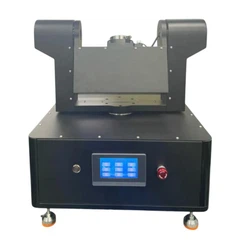
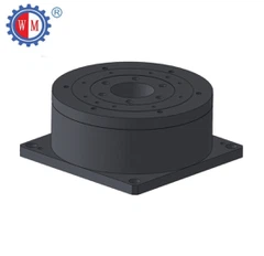
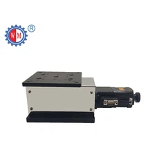
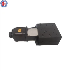
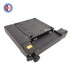
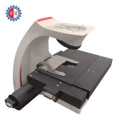
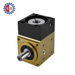
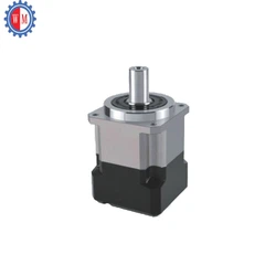
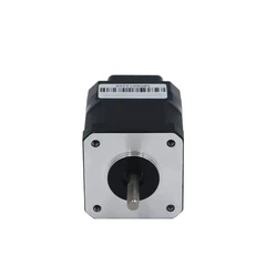


In the realm of precision engineering and automation, motorized rotary tables play a crucial role. As a leading supplier of motorized rotary tables, I often encounter inquiries about the moment of inertia of these devices. Understanding the moment of inertia is essential for optimizing the performance of motorized rotary tables in various applications. In this blog post, we will delve into what the moment of inertia of a motorized rotary table is, why it matters, and how it impacts the overall functionality of these precision instruments.
What is Moment of Inertia?
Before we specifically discuss the moment of inertia of a motorized rotary table, let's first understand the concept of moment of inertia in general. Moment of inertia, often denoted as (I), is a measure of an object's resistance to changes in its rotational motion. In simpler terms, it tells us how difficult it is to start, stop, or change the rotation of an object.
Mathematically, the moment of inertia of a point mass (m) at a distance (r) from the axis of rotation is given by the formula (I = mr^{2}). For more complex objects, the moment of inertia is calculated by integrating this formula over the entire mass distribution of the object.
The moment of inertia depends on two main factors: the mass of the object and how that mass is distributed relative to the axis of rotation. Objects with more mass concentrated farther from the axis of rotation have a larger moment of inertia, meaning they are more difficult to rotate or stop rotating.
Moment of Inertia of a Motorized Rotary Table
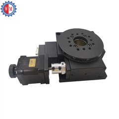
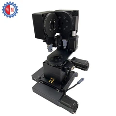
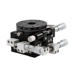
A motorized rotary table consists of a rotating platform, a motor, and various mechanical components. The moment of inertia of a motorized rotary table is the sum of the moments of inertia of all its individual parts.
The rotating platform is a significant contributor to the moment of inertia. If the platform has a large diameter and is made of a dense material, it will have a relatively high moment of inertia. The mass of the payload placed on the platform also adds to the overall moment of inertia.
The motor itself also has a moment of inertia, although it is usually much smaller compared to the platform and payload. The mechanical components such as gears, bearings, and shafts also contribute to the total moment of inertia, albeit to a lesser extent.
Calculating the exact moment of inertia of a motorized rotary table can be a complex task, especially for custom - designed or complex models. However, manufacturers often provide an estimated value of the moment of inertia for their standard products. This value is typically measured in kilogram - square meters ((kg\cdot m^{2})) in the SI system.
Why Does the Moment of Inertia of a Motorized Rotary Table Matter?
The moment of inertia of a motorized rotary table has several important implications for its performance:
1. Acceleration and Deceleration
A motorized rotary table with a high moment of inertia requires more torque to accelerate and decelerate. If the motor does not have enough torque to overcome the moment of inertia, the table may not be able to reach the desired rotational speed quickly or may experience jerky movements during acceleration and deceleration.
For example, in applications where rapid positioning is required, such as in high - speed pick - and - place operations, a rotary table with a lower moment of inertia is preferred. This allows the table to accelerate and decelerate more rapidly, reducing the overall cycle time of the operation.
2. Stability
The moment of inertia also affects the stability of the motorized rotary table. A table with a higher moment of inertia is more resistant to external disturbances, such as vibrations or sudden impacts. This can be beneficial in applications where precise positioning is critical, as it helps to maintain the accuracy of the table's rotation.
On the other hand, in some applications where high - speed rotation is combined with rapid changes in direction, a very high moment of inertia can make the table less responsive and more difficult to control.
3. Motor Selection
The moment of inertia is a key factor in selecting the appropriate motor for a motorized rotary table. The motor must be able to provide enough torque to overcome the moment of inertia and achieve the desired rotational speed and acceleration.
If the moment of inertia is underestimated, the motor may be overloaded, leading to premature failure or reduced performance. Conversely, if the moment of inertia is overestimated, an oversized and more expensive motor may be selected, resulting in unnecessary costs.


Impact of Different Types of Motorized Rotary Tables on Moment of Inertia
As a supplier, we offer a variety of motorized rotary tables, each with its own characteristics and moment of inertia:
Servo Motor Rotary Stage
The Servo Motor Rotary Stage is known for its high precision and excellent speed control. Servo motors can provide precise torque output, which is crucial when dealing with different moments of inertia.
The moment of inertia of a servo motor rotary stage can vary depending on the size of the platform and the type of payload. However, servo motors are designed to handle a wide range of moments of inertia, making them suitable for applications where the load may change or where high - precision positioning is required.
Stepper Motor Rotary Stage
The Stepper Motor Rotary Stage is a cost - effective option for many applications. Stepper motors operate in discrete steps, which can simplify the control system.
Stepper motors have a limited torque output, so they are more suitable for rotary tables with a relatively low moment of inertia. If the moment of inertia is too high, the stepper motor may lose steps, resulting in inaccurate positioning.
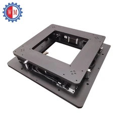
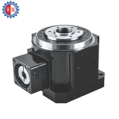
Hollow Rotary Table with Large Open Aperture
The Hollow Rotary Table with Large Open Aperture is designed for applications where cables, pipes, or other components need to pass through the center of the table.
The large open aperture can reduce the overall mass of the table, resulting in a lower moment of inertia compared to a solid - type rotary table of the same size. This can make the hollow rotary table more suitable for applications where rapid acceleration and deceleration are required.
Managing the Moment of Inertia in Motorized Rotary Table Applications
There are several ways to manage the moment of inertia in motorized rotary table applications:
1. Payload Optimization
One of the simplest ways to reduce the moment of inertia is to optimize the payload. This can involve using lighter materials for the payload or reducing the size of the payload. If possible, the mass of the payload should be distributed as close to the axis of rotation as possible.
2. Motor Selection and Tuning
As mentioned earlier, selecting the right motor is crucial. In addition to choosing a motor with sufficient torque, the motor's control parameters can be tuned to match the moment of inertia of the table. This can improve the performance and efficiency of the system.
3. Mechanical Design
The mechanical design of the motorized rotary table can also be optimized to reduce the moment of inertia. For example, using lightweight materials for the platform and mechanical components, or using a more compact design can help to lower the overall moment of inertia.
Conclusion
The moment of inertia of a motorized rotary table is a critical parameter that affects its performance, stability, and efficiency. As a supplier, we understand the importance of providing accurate information about the moment of inertia of our products and helping our customers select the right motorized rotary table for their specific applications.
Whether you are looking for a Servo Motor Rotary Stage, a Stepper Motor Rotary Stage, or a Hollow Rotary Table with Large Open Aperture, we can offer you high - quality products and professional advice.
If you have any questions about the moment of inertia of our motorized rotary tables or need help with your application, please feel free to contact us. We are ready to discuss your requirements and provide you with the best solutions for your motorized rotary table needs.
References
- Meriam, J. L., & Kraige, L. G. (2002). Engineering Mechanics: Dynamics. John Wiley & Sons.
- Shigley, J. E., Mischke, C. R., & Budynas, R. G. (2004). Mechanical Engineering Design. McGraw - Hill.


