
I. Core Logic of Combination: Achieve "Trajectory Expansion" through "Functional Complementarity"
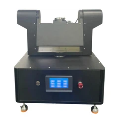
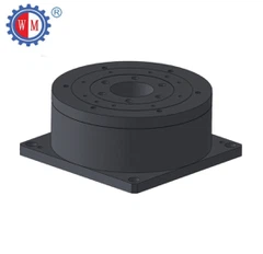
The core value of the high-precision motorized arc stage lies in "precise arc adjustment", but the single rotation function cannot cover the demands such as "spatial position movement" and "height adaptation". The core logic of combining with other stage is: Based on the "rotational degrees of freedom" of the high-precision motorized arc stage, combined with the "linear/lifting/another dimensional rotational degrees of freedom" of different stages, a "1+N" multi-degree-of-freedom motion system is formed, ultimately achieving a compound motion control of "multiple angles in the plane + multiple positions in space". Solve the pain points of "limited movement dimensions" and "single operation scenarios" on a single platform.
Ⅱ. The combination should follow two major principles:
Accuracy matching: The repeat positioning accuracy and resolution of each platform should be at the same order of magnitude (for example, the accuracy of the high-precision motorized arc stage should be ±0.005°, and the accuracy of the matched linear stage should be ≥±0.005mm), to avoid the "short board effect" that lowers the overall accuracy.
Load compatibility: After combination, the self-weight of the upper platform (such as the high-precision motorized arc stage) plus the workpiece load should be ≤ the rated load of the lower platform (such as the lifting platform), and a load allowance of 10%-20% should be reserved to ensure operational stability.
Ⅲ. Typical Combination Schemes: Functions, Structures, and Adapted Scenarios
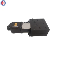
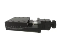
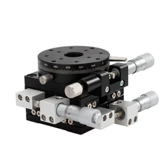
According to different operation requirements, the high-precision motorized arc stage can be combined with a motorized translation table, a motorized lifting table, another motorized arc table, and a manual fine-tuning table.
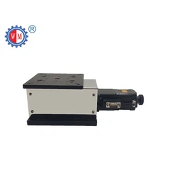
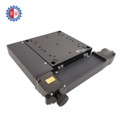
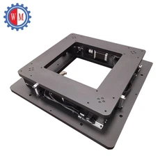
Option 1: high-precision motorized arc stage + XY motorized translation table - A core structure of "rotation + translation" in the plane
Lower layer: XY motorized translation stage, achieving linear motion in the horizontal direction;
Upper layer: The high-precision motorized arc stage is equipped with the workpiece to achieve an arc swing Angle of ±10° or rotation within a specific Angle range.
Control: The synchronous linkage of "translation position + rotation Angle" is achieved through the same control system, supporting preset trajectories (such as translation to point A → arc swing by 10°→ translation to point B → rotation by -15 °).
Core advantage
①It covers the operation requirements of "any position + any Angle within the plane", avoiding errors caused by manual adjustment of position or Angle.
②The translation stage adopts ball screw/synchronous belt drive, combined with the closed-loop control of the high-precision motorized arc stage, and the overall repeat positioning accuracy can reach ±0.002mm (translation) +±0.005° (rotation).
Adapt to scenarios
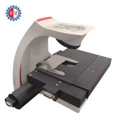
①3C electronic appearance inspection: The translation stage drives the high-precision motorized arc stage to move, enabling the workpiece (such as a mobile phone casing) to be inspected at "different positions + angles" under the visual lens, avoiding blind spots.
②Semiconductor chip welding: The translation stage positions the welding points, and the high-precision motorized arc stage adjusts the Angle of the chips to ensure precise alignment of the pads and improve the welding yield.
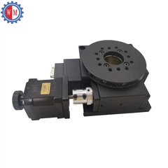
Option 2: Motorized arc stage + motorized rotary stage - Dual-rotation linkage, unlocking precise control of the entire space Angle.
The combination of a motorized arc stage (focusing on high-precision arc adjustment within a specific Angle range, such as ±10° and ±15°) and a motorized rotary stage (focusing on 360° continuous rotation to achieve full-circle motion) builds a "dual-rotation linkage" system through the complementary functions of "finite arc fine-tuning" and "full-circle rotation". It meets the complex scenarios that require "wide-range rotation + small-angle fine adjustment", especially suitable for fields such as precision inspection and automated assembly that have dual requirements for Angle control of "full coverage + local accuracy".
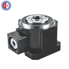
Lower layer: Motorized rotary stage (Z-axis rotation, 360° continuous rotation, supporting infinite full-circle movement): It adopts a large-diameter table surface (commonly φ40mm-φ300mm), with strong load-bearing capacity (usually ≥30kg). Its core function is to drive the workpiece to achieve "wide-range azimuth switching", such as rapid positioning from 0° to 270°.
Upper layer: Motorized arc stage (θ-axis rotation, high-precision adjustment within a limited Angle range, such as ±5°-±30°). It is more compact in size and has a higher repeat positioning accuracy, reaching ±0.005°. Its core function is to complete "fine calibration at small angles" based on the "coarse positioning" of the rotary table, such as fine-tuning from 270°±0.5° to 270°±0.01°.
Typical Application Scenarios: Full-process coverage from "rough positioning" to "fine calibration".
①Multi-directional detection of optical lenses: The lens needs to be precisely adjusted within ±0.1° at each 10° interval within the full range of 0° to 360° to detect imaging distortion in different directions.
②Solution value: The rotating table drives the lens to quickly switch between 10°, 20°... With a coarse positioning Angle of 360°, the high-precision motorized arc stage is fine-adjusted by ±0.1° at each position to ensure that the detection Angle deviation is ≤5 arc sec, and the repeatability of imaging data is improved by 90%.
③Welding of aerospace components: The ring-shaped components of the engine need to be welded with multiple weld points on a 360° circumference, and each weld point should maintain an Angle deviation of ±0.005° from the reference line.
④Solution value: The rotary table enables the full rotation of the annular component (stopping once every 15° of rotation), and the high-precision motorized arc stage fine-adjusts the weld Angle at each pause point to ensure the accuracy of the welding position, reducing the defect rate to below 0.1%.
⑤Solution value: The rotary table controls the azimuth Angle (360° continuous rotation), and the arc table controls the pitch Angle (fine-tuning within ±5°). The two work in tandem to achieve a beam pointing accuracy of ≤3 Arc sec, and the calibration efficiency is increased by three times.
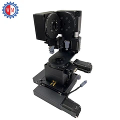
Option 3: Motorized Arc stage A + Motorized Arc stage B - Orthogonal dual-axis orthogonal rotation to construct spatial full-attitude angular position and pose control
When the rotation dimension of A single arc stage cannot meet the complex spatial Angle adjustment requirements, the orthogonal combination of motorized arc stage A and motorized arc stage B (such as θx axis +θy axis) can construct a "dual-axis rotation system". Through the independent control and coordinated linkage of the two axes, precise positioning of the workpiece at any Angle in three-dimensional space can be achieved. It is especially suitable for high-end scenarios that require "multi-angle posture adjustment" and "complex curved surface trajectory movement".
The motorized arc stage A (θx axis) is the "pitch axis", rotating horizontally (such as within ±20° range) to control the pitch Angle of the workpiece. The B θ-yy axis) of the motorized arc stage is the "yaw axis", rotating in the vertical direction (such as within ±10° range) to control the yaw Angle of the workpiece. The rotation centers of the two axes need to precisely converge (with a deviation of 0.01mm).
Typical application scenario: The leap from "planar adjustment" to "spatial attitude"
①Semiconductor wafer inspection: Defect detection on the wafer surface must cover all angles of "horizontal ±15°+ vertical ±20°" to ensure that scratches and particles in different directions can be identified.
②Solution value: The dual-axis arc stage drives the wafer to achieve multi-angle flipping. Combined with the synchronous focusing of the optical lens, the defect detection coverage rate has increased from 60% for the single-axis to 99.9%, and the detection efficiency has been doubled.
③Aero-engine blade processing: The blade profile is a complete,x spatial curved surface. During milling, the blade Angle (pitch ±10°+ yaw ±10°) needs to be adjusted in real time according to the slope of the curved surface to ensure that the relative attitude between the tool and the profile is always optimal.
④Solution value: The dual-axis linkage system generates real-time Angle instructions based on the CAD model, keeping the milling trajectory error within 0.008mm and increasing the blade profile accuracy compliance rate to 98%.
Ⅳ. Summary: The Core Value of the Combination - From "Single Function" to "Scenario-based Solutions"
The combination of the high-precision motorized arc stage and other stages is essentially "taking user needs as the core and integrating scattered motion functions into an integrated system". Whether it is the basic combination of "in-plane translation + rotation" or the complex system of "dual-axis rotation + lifting", they ultimately point to two major values:
Efficiency improvement: Replace manual multi-step adjustment and achieve "one-click" complex trajectory control. For instance, the inspection efficiency of 3C production lines can be increased by 3 to 5 times.
Precision assurance: Through multi-axis coordination and error compensation, the overall motion accuracy is controlled at the micrometer and arcsecond levels, meeting the "zero error" requirements of high-end manufacturing and scientific research.
As automation technology develops towards "multi-dimensional and highly integrated", such combination solutions will become the "standard configuration" in industries such as semiconductors, medical care, and aerospace, promoting precision motion control to move from the "equipment level" to the "system level".


