

How to Adjust the Rotational Speed of a Motorized Rotation Stage Smoothly?
As a supplier of motorized rotation stages, I understand the crucial role that smooth speed adjustment plays in various applications, from precision manufacturing to scientific research. A well - controlled and smoothly adjustable rotational speed can significantly enhance the performance and accuracy of your equipment. In this blog, I will share some effective ways to achieve smooth speed adjustment of a motorized rotation stage.
Understanding the Basics of Motorized Rotation Stages
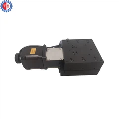
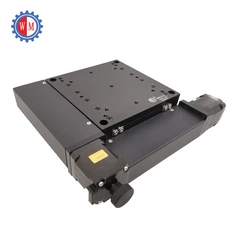
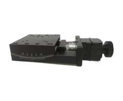
Before delving into the speed adjustment methods, it's essential to have a fundamental understanding of motorized rotation stages. A motorized rotation stage is a device that can rotate an object around a fixed axis. It typically consists of a motor, a transmission mechanism, a control system, and a platform where the object to be rotated is placed.
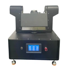
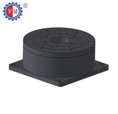
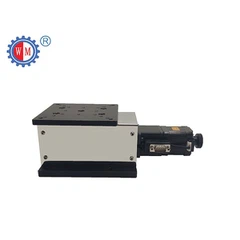
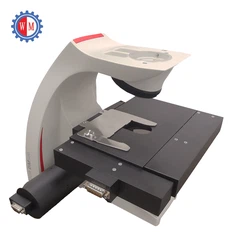
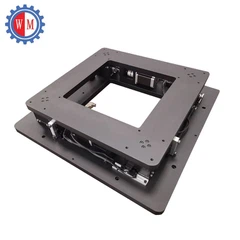
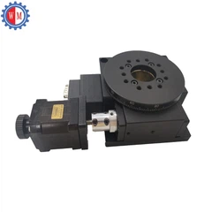
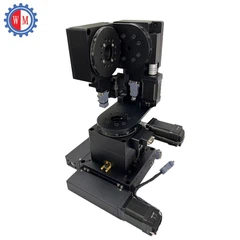
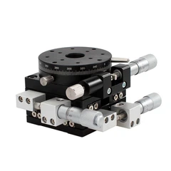
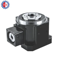
There are different types of motorized rotation stages available in the market. For example, the Motorized Rotary Stage with Worm Gear Device offers high torque and precise positioning due to the unique properties of the worm gear. The Minature Rotary Positioning Stage is designed for applications where space is limited but high - precision rotation is still required. And the Optic Motorized Rotating Stage is specifically tailored for optical applications, providing smooth and accurate rotation for optical components.
Selecting the Right Motor
The choice of motor is the first and most critical step in achieving smooth speed adjustment. Different motors have different characteristics that affect the speed control performance.
Stepper Motors
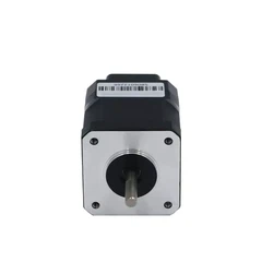
Stepper motors are a popular choice for motorized rotation stages. They move in discrete steps, and their speed can be controlled by adjusting the frequency of the input pulses. One advantage of stepper motors is their ability to hold a position accurately without a feedback system. However, when it comes to smooth speed adjustment, stepper motors may have some limitations. At low speeds, they can produce vibrations and audible noise due to the step - by - step movement. To overcome this, micro - stepping technology can be used. Micro - stepping divides each full step into smaller sub - steps, resulting in smoother motion and reduced vibration.


Servo Motors
Servo motors are another option. They use a feedback mechanism, usually an encoder, to continuously monitor the position and speed of the motor shaft. This allows for very precise speed control and smooth operation over a wide range of speeds. Servo motors can quickly adjust to changes in the load and maintain a constant speed. However, they are generally more expensive than stepper motors and require a more complex control system.
Controlling the Power Supply
The power supply to the motor has a direct impact on its rotational speed. By controlling the voltage or current supplied to the motor, you can adjust its speed.
Voltage Control
For DC motors, adjusting the voltage is a straightforward way to change the speed. A higher voltage will generally result in a higher rotational speed, while a lower voltage will slow down the motor. However, it's important to note that the relationship between voltage and speed is not always linear, especially when the motor is under load. Additionally, over - voltage or under - voltage conditions can damage the motor.
Current Control
Controlling the current flowing through the motor can also affect its speed. By limiting the current, you can reduce the torque output of the motor, which in turn can slow down the rotation. Current control is often used in combination with voltage control to achieve more precise speed adjustment.
Implementing a Smooth Control Algorithm
A well - designed control algorithm is essential for smooth speed adjustment. The control algorithm takes input from the user or a sensor and calculates the appropriate output to the motor to achieve the desired speed.
Proportional - Integral - Derivative (PID) Control
PID control is a widely used algorithm in motor speed control. It consists of three components: proportional, integral, and derivative. The proportional term responds to the current error between the desired speed and the actual speed. The integral term accumulates the error over time and helps to eliminate any steady - state error. The derivative term predicts the future error based on the rate of change of the error and provides a corrective action to prevent overshooting. By tuning the PID parameters (Kp, Ki, and Kd), you can optimize the speed control performance and achieve smooth acceleration and deceleration.
Fuzzy Logic Control
Fuzzy logic control is a more advanced control algorithm that can handle complex and uncertain systems. It uses a set of linguistic rules to approximate human reasoning. In the context of motor speed control, fuzzy logic can adapt to changing conditions and provide smooth speed adjustment without the need for precise mathematical models.
Mechanical Considerations
Apart from the electrical and control aspects, mechanical factors also play an important role in smooth speed adjustment.
Belt and Gear Transmission
If your motorized rotation stage uses a belt or gear transmission system, proper tensioning and alignment are crucial. A loose belt or misaligned gears can cause vibrations and jerks during rotation, which will affect the smoothness of the speed adjustment. Regular maintenance, such as checking and adjusting the belt tension and gear alignment, is necessary to ensure optimal performance.
Load Balancing
The distribution of the load on the rotation stage can also impact the speed adjustment. An unevenly distributed load can cause the motor to work harder on one side, leading to fluctuations in speed. Make sure that the object to be rotated is properly centered and balanced on the platform.
Feedback and Monitoring
Continuous feedback and monitoring are essential for achieving and maintaining smooth speed adjustment. Sensors, such as encoders or tachometers, can be used to measure the actual speed of the motor. This feedback information can be sent back to the control system, which can then make real - time adjustments to keep the speed stable.
In addition, monitoring the performance of the motorized rotation stage over time can help identify any potential issues early. For example, an increase in vibration or noise may indicate a problem with the motor, the transmission system, or the control algorithm. Regularly checking and analyzing the performance data can help prevent breakdowns and ensure the smooth operation of the equipment.
Conclusion
Smoothly adjusting the rotational speed of a motorized rotation stage requires a comprehensive approach that takes into account the selection of the right motor, control of the power supply, implementation of a suitable control algorithm, consideration of mechanical factors, and continuous feedback and monitoring. By following these guidelines, you can ensure that your motorized rotation stage operates efficiently and provides accurate and smooth rotation.
If you are interested in our motorized rotation stages or need more information on speed adjustment techniques, we invite you to contact us for further discussion and potential business cooperation. We are committed to providing high - quality products and professional technical support to meet your specific needs.
References
- Dorf, R. C., & Bishop, R. H. (2016). Modern Control Systems. Pearson.
- Krause, P. C., Wasynczuk, O., Sudhoff, S. D., & Pekarek, S. D. (2013). Analysis of Electric Machinery and Drive Systems. Wiley.
- Fuzzy Logic Toolbox User's Guide. MathWorks.


