
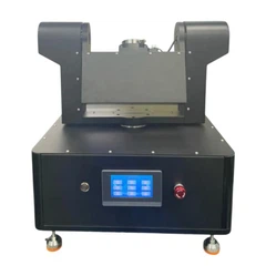
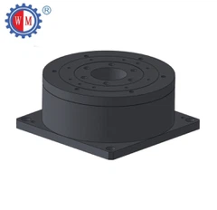

In the work, how to calculate the ratio of the motorized rotary table?
Firstly, we need to know the working principle of the worm gear: A Worm drive belongs to one kind of gear drive, which is used to transfer the motion and power between spatially staggered shafts. Commonly, what we use two-axis staggered Angle ∑=90°. It means the two shafts of the wormwheel and the worm drive cross each other vertically like as below the attached picture:

The worm can be seen as a spiral with one tooth (single head) or several teeth (multiple heads) around the spiral line on the cylinder. The worm wheel is like a helical gear, but its teeth are wrapped around the worm.
In meshing, the worm turns a circle, which will drive the worm wheel to turn a tooth (single head worm) or several teeth (multi worm); Our worm for electric motorized table generally uses 1 head, but special hones have 2 and 4 heads.
Secondly, how to calculate the speed ratio of a motorized rotary table? We need to know the number of worm gears and the worm header.
Reduction ratio I = oformgear number Z2/ worm head number Z1.

(The number of worm head value 1, 2, 4, 6, when the value is much smaller, the transmission ratio is much bigger, when its worm head value is 1, and it has a self-locking function)
Usually, the value we use in our motorized rotary table and stage is 1, so all the electric motorized table we produce has a self-locking function.
What we used the Ratio for the motorized rotary table(i=Z2/Z1)


